Welcome to my first blog post! Even though this might be the first entry, the idea to start such a blog has been with me for ages. But only recently I’ve finally decided set up a small server and install wordpress to start publishing my stuff.
I am having several mobile phones, most of them are old devices I’ve used for some time until I got a new phone. One of these devices is a black Sony Xperia Z1 compact (Z1c) which I liked a lot for its small form-factor. Even though Sony stopped publishing Android updates for this device years ago it is still equipped with up-to-date software (as of writing this entry it is running Android 10) thanks to an active development community over there at xda-developers. The Z1c is one of the oldest phones I’m still using from time to time until lately the battery decided to die. Since it’s been running smoothly otherwise I did not want to give up on it yet so I’ve bought a new (turns out the manufacture date was 2013W50 but thats another story) battery to exchange it. This should have been a trivial process since I’ve disassembled the device a few times already but this time it went a different route.
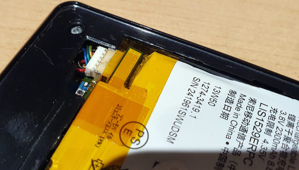
In theory one simply has to remove the backcover, remove a screw, disconnect the connector and finally remove the battery. For attaching a new battery simply follow the steps vice versa. In my case the connector didn’t want to get disconnected, it was attached really tight. By increasing the force I managed to unplug it but I also ripped of half of the solder joints on the PCB side (i.e. on the motherboard of the phone). I realized that only GND pins got ripped of which have been used to permanently attach the connector to the PCB so a quick resolder should have fixed it again. But after fixing the connector for the first time, the battery management was unreliable. Most of the time the operating system of the phone did show the battery percentage as 50% – and it also did not charge. Using the battery charging analysis tool Ampere I was able to identify the temperature sensor not working anymore. The battery temperature was measured as -30°C which is way below my actual room temperature. This rendered my fixed connector useless, I couldn’t use the phone this way because it was only working when being connected to a power supply. In order to continue using this phone I had to come up with another solution.
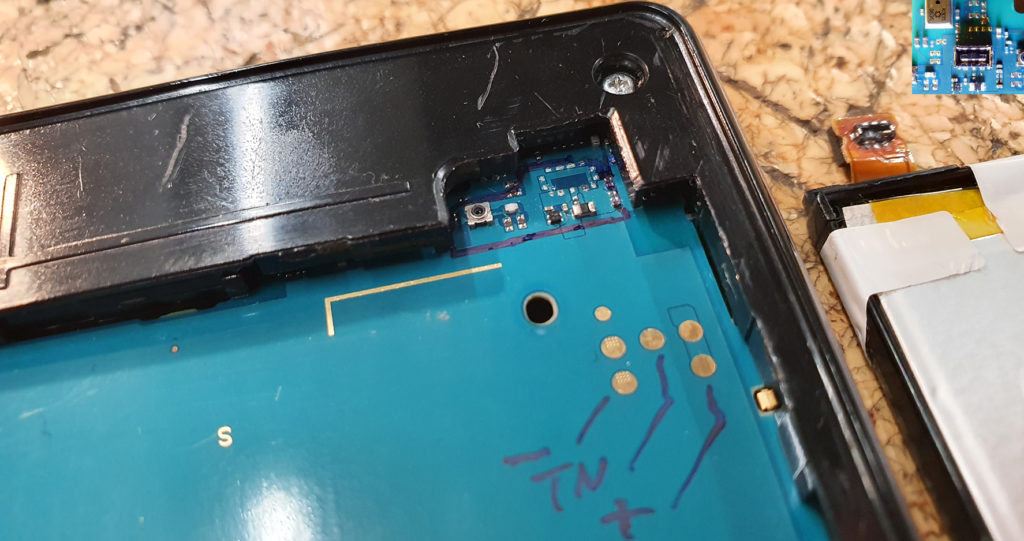
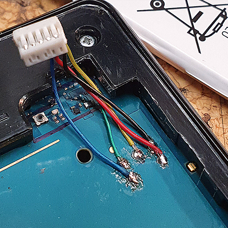
Phone motherboard with removed connector next to the battery that caused all this mess. (On the top right you can see the original state of the PCB with the connector soldered onto it)
The idea was to solder the battery directly to the solder pads but these are really tiny and I’m by far no soldering expert and probably don’t have the right equipment and neither a calm enough hand to solder at such a tiny scale. Thanks to another post at xda-developers I was able to identify bigger solder pads which serve the same purpose as the original ones. I suppose they are test points or an alternative way to power the PCB during development. Those already mentioned pads can be seen in the picture above as well, it’s the group of five (six) pads near the bottom of the picture. The two left solder pads are for GND (the purpose of the smaller third one above is unknown to me), the center one is the temperature sensor (TN) and the two on the right are VCC. I didn’t like the idea of permanently connecting the battery to the phone too much so I had to make it somehow pluggable. Since there’s not much room inside the connector had to be as small as possible and the same applies to the wire diameter since they will be soldered onto the PCB below the battery. The closest fit to these requirements have been the internals of an old Logitech G930 that was lying around. It has flat 5-pin connectors and the wire diameter is very thin (I am assuming that they are thick enough for being used as power supply cables). Even though the battery only features three solder pads (GND, TN, VCC) the connector can be used anyways by modifying the spacing between the pins (aka bending the pins).
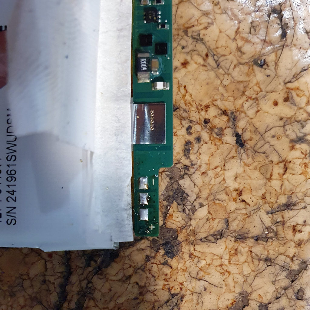
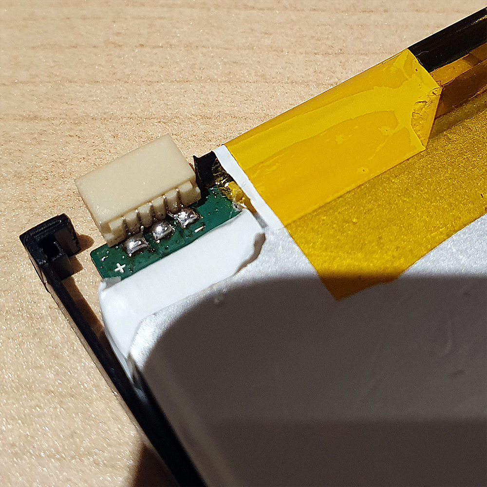
Battery with removed flexcable connector 
New 5-pin connector added to the battery
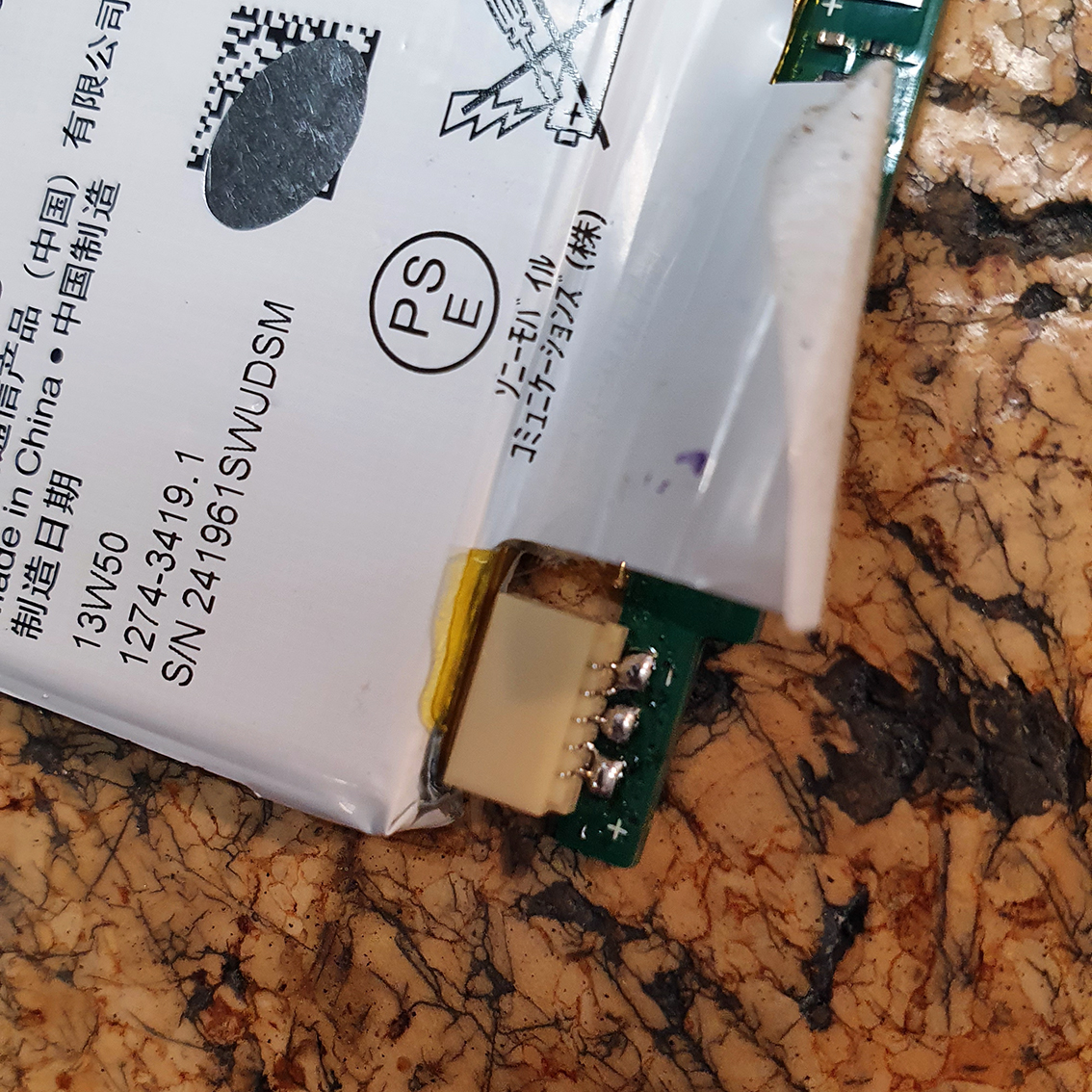
The connector in the picture above is facing backwards because the charging circuit board is bent over by 180 degrees. Therefore it will face frontwards after fixing the orientation. The picture below shows my solder work on the main PCB. I am not a professional in soldering but the joints look OK enough to me.
Solder job on the main PCB 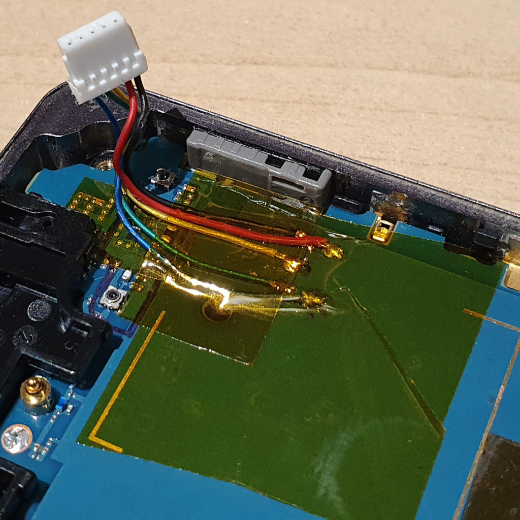
PCB covered with Kapton tape for securing the wires

The final plan was to bend and hide the cables under the black frame where the clipping is. Since the battery will fit in very tightly and probably puts a lot of pressure onto the wiring I decided to put Kapton tape everywhere. All the solder joints, resistors and wires formerly touching are now isolated with the tape. It also might act as some kind of strain relief albeit there shouldn’t apply such kind of force after reassembling it. What’s still missing is finishing the battery job and putting it all back together.
Battery with attached frame 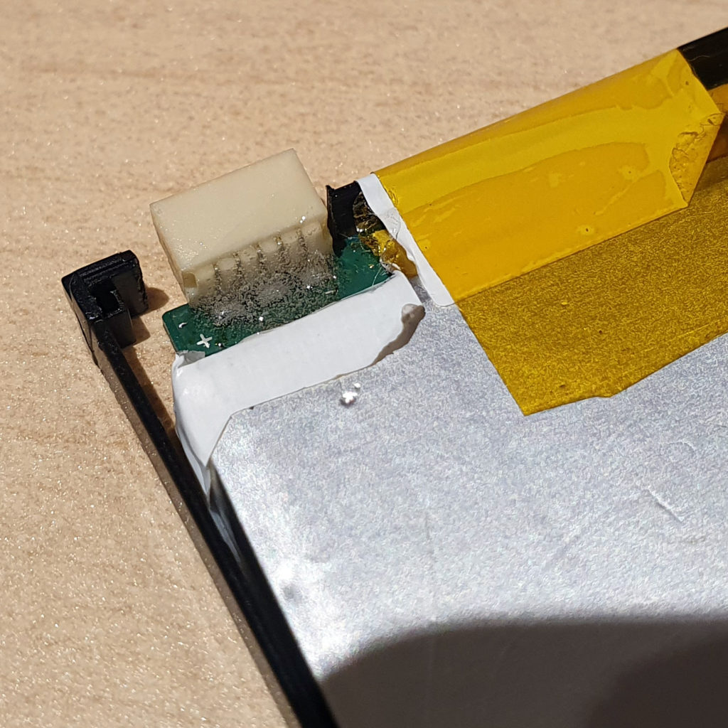
Connector with 2K glue to secure the solder joints

The battery is surrounded by a frame which can be screwed into the phones frame. The new connector needs more space so I cut out a space big enough for it. The frame is simply taped onto the battery which I extended with even more Kapton tape. After reassembling it the battery indeed has an even tighter fit but it is still tolerable. I am a bit unsure about the codition of the wiring stuffed below the frame but after checking, the isolation appears to be undamaged. I will store the phone in a LiPo-safe battery bag anyways for minimizing the risk of malfunctions due to this modification. The final result can be seen below.